Overview
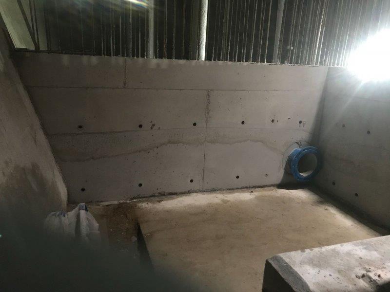
The Red Cow Service Reservoir (SRV) which is a buried concrete structure, is south of Maestag, providing water supply to Maestag town and the surrounding area.
Built in the 1920s, this 4.1 megalitre reservoir required a comprehensive condition survey and a feasibility study for long-term repairs, along with potential alterations to improve network resilience.
Mason Clark Associates (MCA) was commissioned to undertake these critical tasks, ensuring the structural integrity of the reservoir and preparing it for future demands.
Challenges and Solutions
The Red Cow SRV project required detailed investigative work and careful design solutions to meet modern standards while overcoming several challenges:
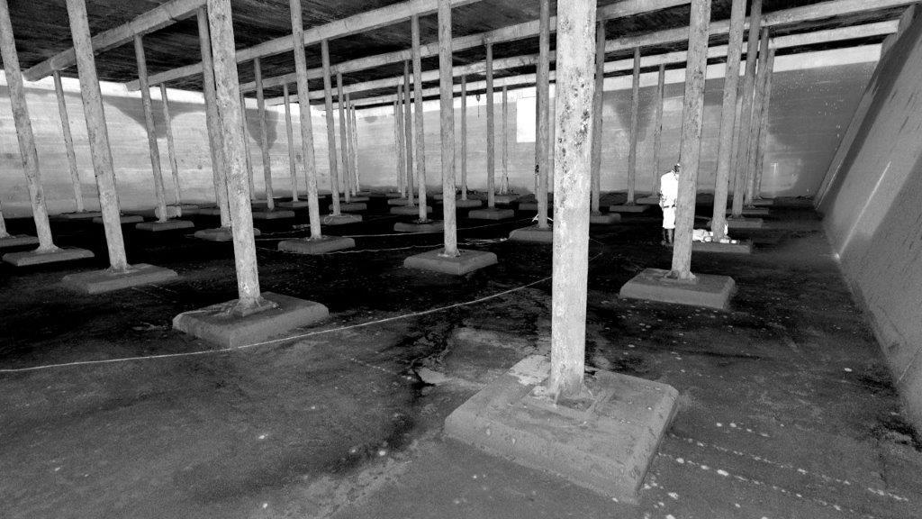
- Structural integrity assessment: we conducted an extensive condition survey of the reservoir, including 3D laser scans and non-destructive testing (NDT) of concrete and steel elements. The survey provided essential data on the reservoir's structural condition, informing future investment and repair strategies.
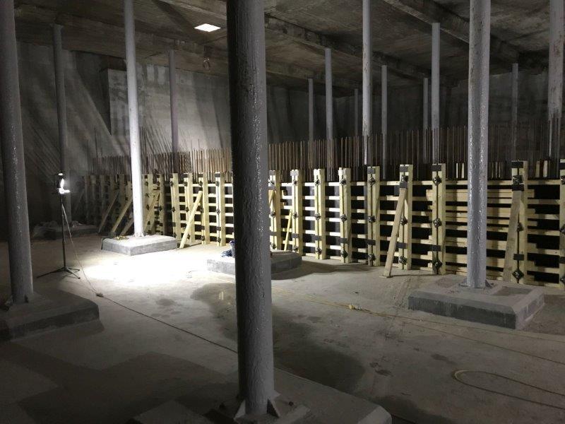
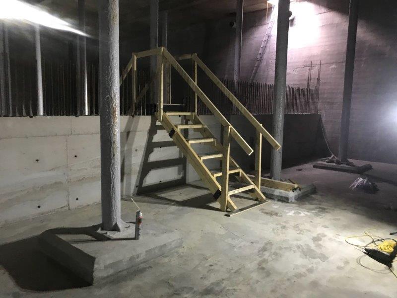
- Complex testing and analysis: given the reservoir’s age and buried location, testing required confined spaces-trained personnel. Destructive testing (150mm cores and 25mm drill holes) and non-destructive methods were employed to assess the condition of critical elements, including cast iron columns and concrete structures. These tests helped us to develop a repair strategy that addressed issues such as carbonation, delamination and corrosion.
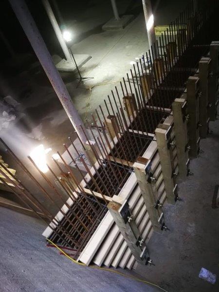
- Reservoir compartmentalisation: to improve operational flexibility and resilience, we designed a permanent full-height concrete dividing wall to create two separate compartments. This 400mm thick cantilever retaining wall was engineered to not exceed the load limits previously calculated for the existing floor slab, ensuring the new structure’s compatibility with the original reservoir design.
MCA's Contribution
We provided comprehensive survey and design services to ensure the long-term integrity and functionality of the Red Cow Service Reservoir. Our scope included:
- Condition survey: using 3D laser scans and a range of NDT methods, we documented the condition of all internal elements, including the roof, walls and floor. The detailed findings were compiled into a condition report, along with recommendations for repairs and future upgrades.
- We developed the design for the internal dividing wall, ensuring that the structure met all load-bearing requirements and improved the reservoir’s operational Permanent works design: efficiency.
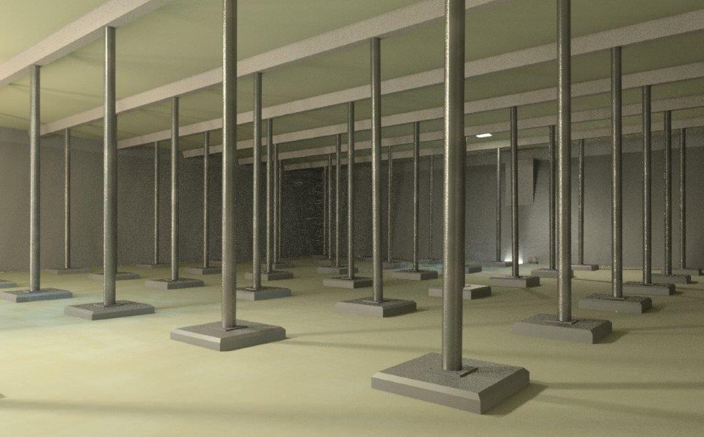
- BIM modelling: the survey data was used to generate a full 3D Revit BIM model, which was provided to the asset owner for use in hydraulic modelling. This model allowed the owner to simulate fluid movement, identify areas of intense mixing and address potential dead spots.
Results
We successfully delivered a comprehensive condition assessment and structural solution for the Red Cow Service Reservoir. Key outcomes include:
- The design of a new dividing wall, enhancing the operational flexibility of the reservoir by allowing it to function as two separate compartments.
- Detailed repair recommendations to prevent further carbonation and corrosion of the concrete roof slab, ensuring the longevity of the structure.
- A complete 3D BIM model, enabling the client to optimise hydraulic performance through detailed simulation and analysis.
Our innovative approach to both surveying and structural design has provided the client with a robust, future-proof solution for one of their critical infrastructure assets.
Click Images to view full size